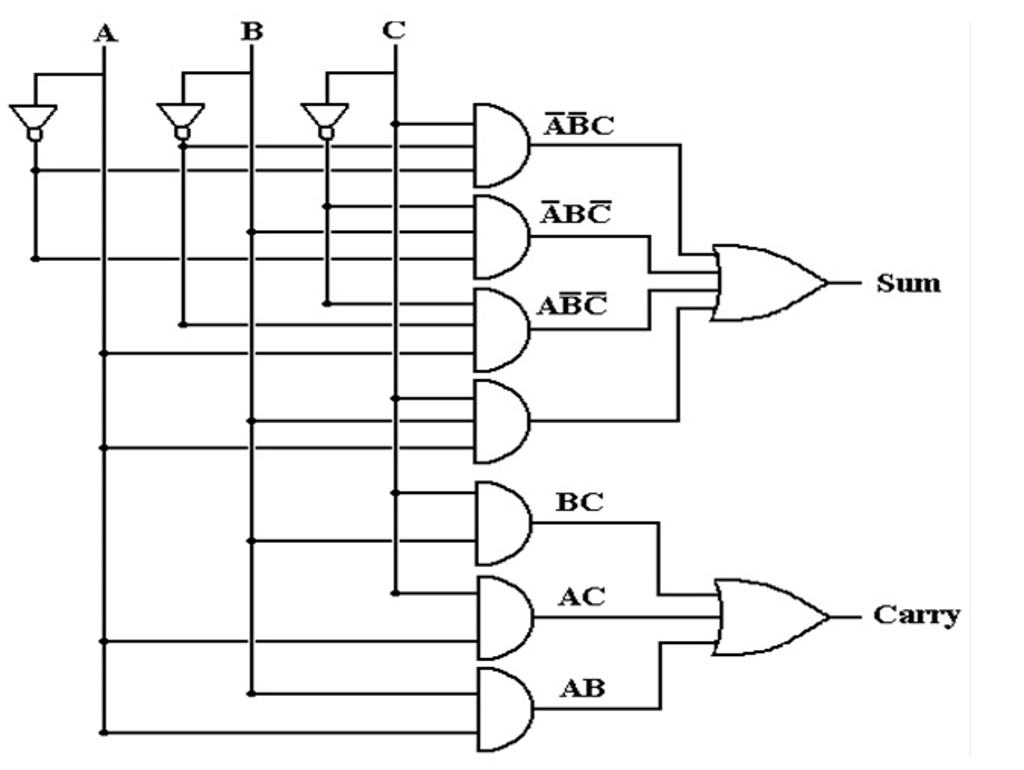
Full Adder Logic Circuit Diagram
Adder circuit sum carry logic circuits electronics combinational using boolean expression two implementation both tutorial simplified below figure Full adder circuit diagram Full adder circuit diagram
Half Adder Logic Diagram And Truth Table / OBE Assignment: Digital
Adder circuit understanding Adder logic half implementation Adder logic
Adder bit circuit subtractor ripple carry logic diagram using project only digital its computing learn let build single indie electronics
Full adder logic circuit.Full adder Full adderDigital logic.
What is full adderHalf adder and full adder Full adder circuit diagramAdder logic projectiot123 introduction binary carry sum outputs.

Adder circuit logic using boolean digital function diagram implementation implement
Adder diagram circuitAdder circuit two add half gate subtractor delay combinational numbers addition find table circuits truth code logic diagram binary adders Let's learn computing: 4 bit adder/subtractor circuitAdder circuit logic diagram pla using symbol explain inputs outputs.
5 logic circuitsFull adder circuit diagram Adder diagram circuit digital electronics logic exampleAdder logic block watelectronics circuits.

Adder circuit construction binary circuits qiskit sourav gupta
Adder half truth circuitdigestHalf adder logic diagram and truth table / obe assignment: digital Explain full adder circuit using pla having three inputs, 8 productFull adder equation.
Adder xor rangkaian transistor ripple pengertian kombinasiAdder bit circuit logic half make gates diagram comparator two electronics first questions cout difference between there only simple second Adder geeksforgeeksDigital electronics: adder.

Adder circuits arithmetic logic diagram meant circuit given below
[diagram] bcd adder circuit diagramLogic gates Adder transistor logic gatesAdder circuit half bit carry ripple schematic diagram logic gate truth table digital delay perform without computer xor assignment seventh.
Full adder logic diagram and truth table : what is a 2-bit full adder12+ half adder schematic [diagram] full adder circuit diagram and truth tableFull adder circuit using logic gates.

What is half adder and full adder circuit?
Full adder logic diagram and truth tableAdder circuit binary logic output xor boolean electronics diagrams derived Adder carry circuit sum logic implementation output electronics simplified two outputs combinational circuits tutorial both shows below figureFull adder logic gate circuit diagram template logic logic gates.
Full adder logic diagram and truth table diagram logic diagram fromAdder logic circuit circuits figure What is parallel binary adder?Digital logic design: full adder circuit.

Full adder circuit: theory, truth table & construction
Block diagram of basic full adder circuitAdder binary parallel bit logic diagram circuit electronics between Adder libretexts truth adders circuitsFull adder.
What is meant by arithmetic circuits? .

Full Adder Equation

Full adder logic circuit. | Download Scientific Diagram

Half Adder Logic Diagram And Truth Table / OBE Assignment: Digital

Full Adder Circuit Diagram

logic gates - How to make 2 bit or more half adder circuit - Electrical

Full Adder Logic Diagram And Truth Table : What is a 2-bit full adder