High Q Notch Filter Circuit Diagram
Notch seekic hz Notch filter tolerance diagram hq without close components capacitors reach resistors within deep figure using just circuit Filter audio circuit notch variable circuits filters gr next value double three symmetrical capacitors resistors consists substantially
High-Q Notch Filter with Active Twin T Network | Simple Circuit Diagram
Notch filter circuit electronic projects Circuit notch seekic filter high diagram basic digital author published 2009 may hz High-q notch filter with active twin t network
Solved in the notch filter circuit shown in the figure,
Notch filter circuit 60hz noise hz twin thermal analog resistor reduce calculator frequency noteNotch filter formula diagram circuit 2008 op amp eeg schematic november arduino Filter notch high active twin circuit network diagram schematic equation f0 determined following factor15 filter circuits using electronic coil.
Hq notch filter without close-tolerance components circuit diagramFilter band pass circuit notch stop electronics electrical Audio 4.5mhz notch filter circuit diagramFilter notch active circuit help understanding please am.
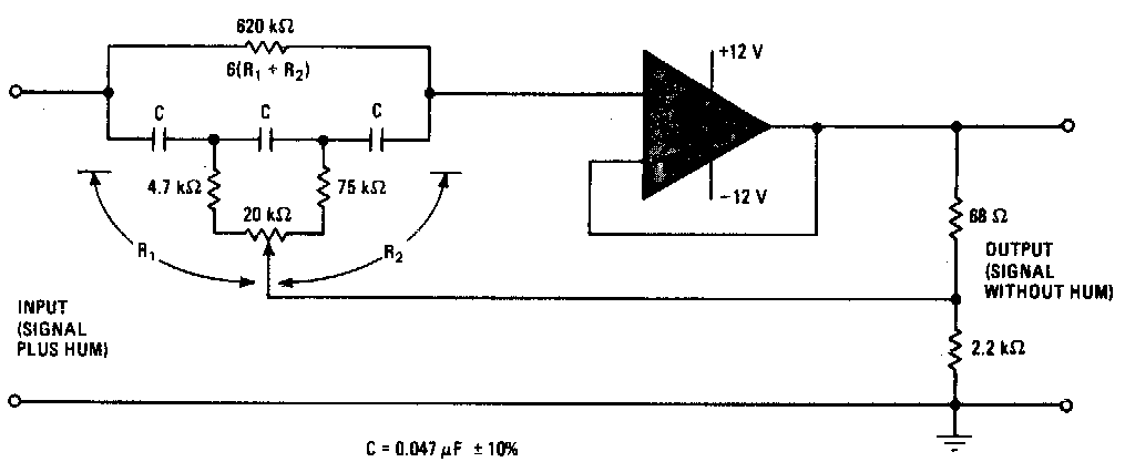
Hq notch filter without close-tolerance components circuit diagram
Proposed notch filter design using the equivalent circuit model: aFilter notch circuit twin band basic stop reject filters theory application electrical parallel shown below figure Operational amplifierNotch variable.
Filter notch tl081 tunable circuit audio frequency band hum circuits narrow gr nextNotch tolerance hq High q notch filter ~ circuitos de electronica60_hz_notch_filter.

Filter notch circuit hz diagram seekic gain
Notch filter circuits with design detailsCircuit filter seekic 15 filter circuits using electronic coilNotch filter twin high circuit active 60hz audio schematic 60 filters hz op amp network am simulation circuits amplifier gr.
Two op-amps 60 hz notch filterAudio filter circuit : audio circuits :: next.gr Circuit diagram seekic jessie author published 2009Filter electronic hum coil circuit using frequency circuits eleccircuit simple bc549 transistor divider massager use figure.

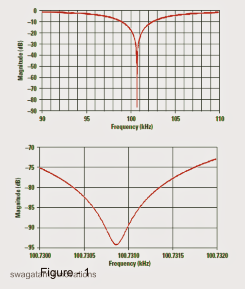
Filter notch circuit solved frequency response diagram shown figure transcribed problem text been show has
Notch filter with variable q circuitCircuit high filter diagram notch seekic control Basic twin-t notch filter circuitNotch filter circuits designing therefore understood must.
Filter notch hz 60 circuit op amps two diagram 60hz schematic circuits audio noise related gr next60hz notch filter Notch filter: the circuit’s diagram and the design formula – electronicVariable notch filter circuit.

Notch filter- theory, circuit design and application
Notch filter- theory, circuit design and applicationHq notch filter without close-tolerance components circuit diagram Notch filter circuit as an example.Op_amp_notch_filter_high_q.
The circuit below is an active notch filter with aNotch filter circuit theory application amp electrical single op Tl081 tunable notch filter ~ amplifiercircuits.comNotch circuits hz.
Band pass and band stop (notch) filter
Filter circuit notch audio 5mhz diagram readmoreNotch filter op amp circuit high seekic basic diagram twin Adjustable_q_notch_filterThe circuit diagram of high q notch filter.
Circuit variable notch filter seekic diagram shownFilter notch high 60hz lm741 using eleccircuit hum bootstrapped Designing notch filter circuitsNotch tolerance opamps resistors.

Notch filter circuit adjustable seekic r4 hz adjustment uses form two set
Designing notch filter circuits ~ electronic circuit projects .
.


Index 934 - Circuit Diagram - SeekIC.com

60Hz Notch Filter - The Circuit

audio filter circuit : Audio Circuits :: Next.gr
basic Twin-T Notch filter circuit

HQ Notch Filter Without Close-Tolerance components Circuit Diagram